
|
QLF Filter Assembly Procedure |
| Schematic | Next Page |
I recommend that you construct the circuit on a prototype board initially, in order to become familiar with the circuit. In this way, it will be easier to plan how you want to package the device for your application.
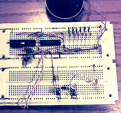
The photo below shows my assembly on two Radio Shack prototype boards.
The microprocessor is on the upper left. You can also see the crystal and
reset circuit. Next to it is the 74LS240. Then the 6 LEDs followed by the
speaker driver transistor.
On the bottom half is the rig keying circuit and the temporary LED to
see it working.
 When you construct the circuit in it's final package, you may want to
use a metal or shielded box to help reduce RFI. Be sure you use a
good source of 5V, since the logic requires TTL voltages. You may want to
add connectors and a permanent speaker. Plan how you want to display the
LEDs. You may want to add switches to control the power or the speaker.
When you construct the circuit in it's final package, you may want to
use a metal or shielded box to help reduce RFI. Be sure you use a
good source of 5V, since the logic requires TTL voltages. You may want to
add connectors and a permanent speaker. Plan how you want to display the
LEDs. You may want to add switches to control the power or the speaker.
Take your time and enjoy the project. I have constructed lots of kits over the years, and by far, the most enjoyable part is the construction and the pride of doing the best possible job.
If you have any comments, please drop me a note. You can find me at